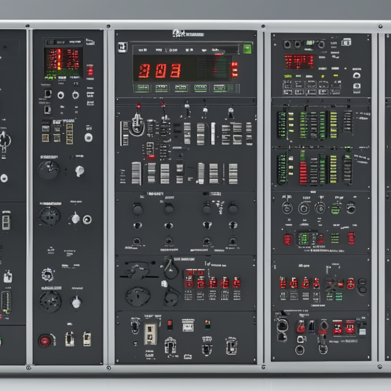
Selecting the best automatic transfer switch in 2026 requires more than comparing current ratings and catalog prices. A Power Automat Transfer Switch must move a critical load from utility power to a generator or secondary source without creating dangerous interruptions. Hospitals, data centers, factories, and commercial buildings each face different risks. A brief voltage dip may be tolerable in lighting, but unacceptable for servers, pumps, or medical equipment. The switch becomes the quiet decision-maker behind the wall.
This guide examines open-transition, closed-transition, delayed-transition, bypass-isolation, and service-entrance transfer switch types. It considers sensing accuracy, switching speed, short-circuit withstand ratings, maintenance access, communications, and generator compatibility. Field commissioning reports often reveal practical problems that brochures overlook, including loose control wiring, poor neutral handling, and confusing alarm signals. Small details matter.
It is not always the largest model.
A reliable selection process should match the switch to the facility’s load profile, transfer sequence, fault level, and required code compliance. Standards such as NFPA 110, NFPA 70, and applicable IEC requirements may influence the design, but local approval remains essential. Manufacturer testing, documented installation procedures, and qualified inspection provide stronger confidence than marketing claims alone. Even experienced teams can misjudge future expansion or underestimate maintenance space. That weakness deserves attention. The following overview compares the leading types and explains where each design performs well, where it may struggle, and which questions buyers should ask before approving a 2026 installation.
A power automatic transfer switch is an electrical device that moves a critical load between two power sources. Usually, it connects utility power to a generator or backup supply. It monitors voltage, frequency, and phase conditions. When the primary source fails, the controller sends a transfer command. The mechanism then changes connections safely. It also returns the load when stable power is restored.
Open-transition models disconnect one source before connecting another. They are widely used and generally simpler to maintain.
Closed-transition models briefly connect both sources during transfer. This can reduce interruptions, but synchronization and protection settings require careful engineering.
Delayed-transition models pause between sources. That pause helps discharge motors and sensitive equipment.
Selection depends on load characteristics, fault levels, installation space, and required transfer time. A hospital circuit may need different protection than a small pump. Check continuous current ratings, short-circuit withstand ratings, neutral switching, and manual bypass options.
Field inspections should also verify cable torque, enclosure condition, and exercise-test records. The label alone is not enough. A higher-rated switch is not automatically better. Incorrect settings can delay transfer or stress equipment.
Standards and local electrical rules must guide the final design. Real installations can be less tidy than diagrams. Planning for maintenance access is easy to overlook.
2026 Best Power Automatic Transfer Switch Types?
Power automatic transfer switches keep essential loads supplied when the normal source fails. Their operation begins with continuous voltage monitoring. A controller checks phase balance, frequency, and source stability. If readings move outside set limits, it starts the standby generator when required. Then, the switch disconnects the normal source and connects the emergency source.
The timing matters. A short delay prevents transfers during brief voltage dips. Mechanical or electronic interlocking helps prevent both sources from connecting together. Open-transition switches create a short break between sources. Closed-transition models overlap sources briefly, reducing interruption. Bypass-isolation designs allow technicians to service the main mechanism while critical equipment remains powered.
Small details affect real performance. A hospital panel may transfer life-safety circuits within seconds. A factory may need adjustable delays for motors and compressors. Operators should inspect terminals, test alarms, and simulate source failure under safe procedures. Batteries, control wiring, and sensing devices deserve equal attention. They are easy to overlook. No arrangement is perfect. Poor settings can cause nuisance transfers, while delayed maintenance can hide contact wear. Periodic testing with measured results gives engineers better evidence than a simple status light. The best type depends on load behavior, transfer tolerance, maintenance access, and the reliability of each power source.
2026 Best Power Automatic Transfer Switch Types?
Main Types of Automatic Transfer Switches in 2026
Automatic transfer switches are becoming more important as facilities add servers, medical equipment, and battery systems. The IEA’s Electricity 2024 report projects data-center electricity demand will more than double by 2026, exceeding 1,000 TWh globally. That growth increases pressure on transfer speed, fault detection, and maintenance access.
Open-transition ATS units remain common in commercial buildings. They briefly disconnect the load before connecting the backup source. This design is practical and cost-effective, but sensitive equipment may restart. Closed-transition ATS units overlap sources for a short period, reducing interruption during testing. They require careful protection coordination. Delayed-transition models add a programmed pause, helping motors discharge before reconnection. This suits pumps, elevators, and large HVAC systems.
Different loads need different answers. Static transfer switches move critical electronic loads within milliseconds, often supporting data rooms and industrial controls. Bypass-isolation ATS units allow technicians to service the switch without shutting down the load. That detail matters in hospitals and continuous-process facilities. IEC 60947-6-1 provides a useful reference for transfer switching equipment, but field conditions still decide performance. A neat classification can mislead. Poor cable sizing, weak generator controls, or neglected batteries can defeat an excellent ATS. In practice, verify fault current, neutral switching, transition timing, and test records before selecting the “best” type.
2026 Best Power Automatic Transfer Switch Types?
How to Compare Transfer Switch Features and Ratings
Choosing the best automatic transfer switch starts with the load, not the product name. Open-transition switches suit most emergency systems because they disconnect one source before connecting another. Closed-transition models reduce power interruptions but require compatible sources and careful utility approval. Delayed-transition designs help protect motors by allowing residual voltage to decay. In field inspections, the wrong choice often comes from ignoring motor-starting current.
Compare voltage, continuous amperage, frequency, and pole configuration. A three-phase facility may need switched neutral control, especially with separately derived generators. Check the short-circuit current rating, withstand and closing rating, and service-entrance suitability. These values must match the available fault current at the installation point. Also examine transfer time, sensing accuracy, manual operation, bypass capability, enclosure protection, and environmental limits. A higher ampere rating alone does not guarantee safe performance.
Tips: Record the actual loads first. Include pumps, compressors, heaters, and sensitive electronics. Verify generator compatibility under starting conditions, not only steady operation. Ask for tested ratings and installation guidance from qualified professionals. One detail is easy to miss: control wiring length can affect sensing reliability. I would also recheck neutral switching and fault calculations before approval, because assumptions made during design may not match the completed site.
| Transfer Switch Type | Transfer Method | Typical Transfer Interruption | Recommended Applications | Key Advantages | Main Limitations | Important Features to Compare | Typical Rating Considerations |
|---|---|---|---|---|---|---|---|
| Open-Transition ATS | Break-before-make: the normal source disconnects before the emergency source connects. | Usually several cycles Actual time depends on controller settings, source conditions and switching mechanism. | Commercial buildings, residential backup systems, standby generators and general low-voltage loads. | Simple operating sequence; widely available; prevents the two sources from being connected together during normal operation. | Produces a short power interruption; may restart sensitive loads or interrupt processes that require continuous power. | Adjustable time delays; source-voltage and frequency sensing; phase-sequence monitoring; generator start contacts; manual test function. | Verify continuous current rating, short-circuit withstand or closing rating, voltage, frequency, number of poles and neutral switching requirements. |
| Closed-Transition ATS | Make-before-break: the emergency source briefly parallels with the normal source before the normal source disconnects. | Typically less than 100 ms Some loads may experience little or no noticeable interruption when source conditions are suitable. | Data centers, healthcare facilities, manufacturing lines and other loads sensitive to momentary power loss. | Minimizes load interruption; supports periodic generator testing under load without interrupting critical equipment. | Requires source synchronization and compatible protection settings; usually costs more and requires stricter installation controls. | Synchronism-check logic; maximum paralleling time; in-phase monitoring; utility permission requirements; reverse-power and overcurrent coordination. | Confirm suitability for the available fault current, utility interconnection rules, generator controls, voltage class and permitted paralleling duration. |
| Delayed-Transition ATS | Break-before-make with a programmed neutral or load-disconnect interval between sources. | Application-dependent The programmed delay may range from a short interval to several seconds. | Systems with large motors, transformers, capacitors or residual voltage that could cause high inrush current during immediate retransfer. | Allows motor fields and transformer flux to decay; reduces the risk of out-of-phase transfer and nuisance tripping. | Creates a longer interruption; unsuitable for loads that cannot tolerate a delayed restoration without UPS or ride-through support. | Adjustable neutral position time; load-shed controls; retransfer delay; motor-load compatibility; residual-voltage sensing. | Check pole configuration, neutral design, transfer timing range, motor starting requirements and the short-circuit rating of the complete assembly. |
| Bypass-Isolation ATS | A main automatic transfer section is combined with a bypass and isolation path for maintenance. | Depends on operating mode Normal automatic transfer performance is maintained when the main section is in service. | Hospitals, emergency systems, industrial plants and facilities requiring maintenance without removing the load from an available source. | Enables inspection, testing or replacement of the automatic section while maintaining source availability. | Larger enclosure and higher installation cost; more complex operating procedures and interlocking requirements. | Mechanical and electrical interlocks; visible isolation position; bypass source selection; safe test position; maintenance access. | Rate the automatic section and bypass path appropriately; verify withstand rating, grounding, enclosure rating and the facility’s maintenance procedure. |
| Service-Entrance ATS | An ATS designed and marked for installation at the service entrance when permitted by the applicable electrical code. | Based on selected transition type | Buildings where the transfer equipment is installed ahead of downstream distribution equipment and may serve as the main disconnect. | Can integrate service disconnect functions, source protection and emergency-source transfer in one location. | More demanding requirements for accessibility, grounding, overcurrent protection, labeling and utility approval. | Service-entrance marking; suitable main disconnect arrangement; neutral bonding configuration; overcurrent protection coordination; code-compliant enclosure. | Confirm service voltage, ampere rating, available fault current, short-circuit rating, number of poles and local authority requirements. |
| Contactor-Based ATS | Uses electrically operated contactors to transfer the load between sources. | Fast to moderate Timing varies with the contactor mechanism and controller. | Light commercial, residential, small industrial and generator applications with moderate switching duty. | Compact construction; comparatively simple design; often economical for lower-current applications. | Contact wear can increase with frequent switching; may provide less fault-closing capability than a circuit-breaker-based design. | Utilization category; mechanical endurance; coil voltage; contact position indication; short-circuit protective-device coordination. | Compare continuous current, horsepower or motor-load capability, withstand rating, pole arrangement and switching duty rather than current rating alone. |
| Circuit-Breaker-Based ATS | Uses electrically operated circuit breakers or molded-case switching devices to connect and disconnect sources. | Moderate Transfer time depends on breaker operating time and controller logic. | Higher-current distribution systems, service equipment and installations requiring strong fault protection or integrated overcurrent functions. | Can provide higher interrupting capability, selective protection and more flexible system coordination. | Typically larger and more expensive; breaker operating mechanisms may require additional maintenance. | Interrupting rating; short-time withstand rating; trip-unit settings; interlocking; arc-flash coordination; remote status contacts. | Confirm the available fault current does not exceed the marked rating and coordinate trip settings with upstream and downstream protective devices. |
| Three-Phase ATS | Transfers a three-phase load between two compatible three-phase sources. | Based on transition mode | Commercial HVAC, pumps, elevators, industrial machinery, data-center distribution and three-phase generator systems. | Supports balanced three-phase distribution and large motor loads; can monitor phase loss, phase reversal and voltage imbalance. | Incorrect phase sequence, imbalance or neutral configuration can prevent transfer or damage equipment. | Phase-loss sensing; phase-sequence sensing; voltage imbalance limits; frequency monitoring; neutral switching requirements. | Match the system voltage, frequency, phase configuration, pole count, continuous current and motor-starting characteristics. |

Choosing the right automatic transfer switch begins with the load, not the catalog. Identify the normal source, standby source, voltage, phase, frequency, and continuous current. Check motor starting currents, heating equipment, pumps, and sensitive controls separately. A switch rated only for running load may fail during startup.
Match the transfer method to your system’s operating needs. Open-transition units briefly disconnect both sources and suit many standard backup systems. Closed-transition units reduce interruption but require compatible sources and careful synchronization. Delayed-transition models help discharge residual voltage from motors before connection. For critical facilities, bypass-isolation designs can support maintenance without shutting down essential loads. Confirm short-circuit ratings, pole configuration, neutral switching, enclosure protection, and environmental temperature.
Control features deserve equal attention. Verify adjustable time delays, source monitoring, generator start contacts, manual operation, alarms, and communication interfaces. Test the switch with the actual generator and representative loads, not only with a small test lamp. Field inspections often find loose terminals, undersized conductors, or poor neutral arrangements. Small details matter.
A common mistake is choosing by amperage alone. It looks efficient, but it can create expensive limitations later. Review the installation with a qualified electrical professional and the applicable local requirements. Document each setting. Then test failure, restoration, and manual bypass conditions before the system is needed.
Hein Minnie
Cell nr: +27 (0) 82 564 6501
Email: sale@thecirclemachine.com
Hein Minnie Jnr
Cell nr: +27 (0) 84 284 7234
Email: sale@thecirclemachine.com
Address:
10 Apsey Street,
Heidelberg,
Gauteng,
1441
Bendet Engineering Services (PTY) LTD was established in 1987. Our team of engineers and draughtsman are ready to deliver a complete turnkey solution, from the design phase to commissioning. A dedicated team that consists of electrical, mechanical and industrial engineers, we are able to offer a comprehensive service to our clients.