How to Choose the Right Steel Cable Tray for Your Project
Choosing the right Steel Cable Tray is not a simple matter of matching width to cable volume. It affects heat control, maintenance access, grounding continuity, and long-term installation safety. A crowded tray may look efficient during construction. Later, it can restrict airflow, complicate inspections, and make new cable additions unnecessarily difficult.
Electrical engineer David B. Durocher offers a useful reminder: “A cable tray is part of the electrical system, not merely a support.” That principle should guide every selection decision. Project teams should examine cable type, conductor weight, span length, environmental exposure, corrosion risk, and required load capacity. A galvanized steel tray may suit an indoor commercial area. A stainless steel option may perform better near moisture, chemicals, or salt air. Small details matter.
Measure twice.
This guide will compare ladder, perforated, solid-bottom, and wire-mesh designs. It will also explain how tray depth, rung spacing, fittings, covers, and support intervals influence performance. Manufacturer load tables and applicable electrical standards must remain central to the decision. Practical experience matters too. I have seen installations fail through poor access planning, not weak materials. That lesson is easy to overlook.
No single Steel Cable Tray fits every project. The cheapest option may create higher labor costs later. The strongest tray may be unnecessary for a lightly loaded route. Selection becomes more reliable when engineers balance present requirements with future expansion. Even then, assumptions deserve review. Project conditions change, and a neat drawing can hide an awkward site reality.
Define Cable Load and the NEC 40% Fill Requirement
Choosing a steel cable tray starts with two separate questions: How much cable will it carry, and how much space will those cables occupy? NFPA 70, 2023 Edition, Section 392.22(B)(2), limits three or more multiconductor cables to 40% of the tray’s usable interior area. This is a maximum, not a design target. Measure each cable’s actual outside diameter, calculate its cross-sectional area, and compare the total with the tray’s internal area. A 600 mm-wide tray may not provide 600 mm of usable width after fittings, side rails, or covers are considered.
Cable load also includes weight. Add the mass of installed cables, planned additions, and a practical allowance for movement or maintenance. NEMA VE 1 defines cable tray load and span classifications, while NEMA VE 2 provides installation guidance for supports, joints, and field conditions. Select a tray whose tested load rating exceeds the calculated load at the actual support span. Do not copy a rating from a shorter span.
Leave room for change.
In real projects, cable schedules are often incomplete during early design. I have seen a tray pass the 40% calculation, then fail after larger control cables were added. That mistake is easy to make. Recheck fill and loading after routing changes, especially near vertical bends and crowded terminations. The 40% rule supports ventilation and installation access, but it does not replace ampacity checks, temperature correction, or structural review. A neat calculation can still be wrong when its input data is weak.
How to Choose the Right Steel Cable Tray for Your Project
Define Cable Load and the NEC 40% Fill Requirement
Design basis: The chart assumes a 4-inch usable tray depth and compares the maximum cable cross-sectional area permitted at 40% fill for common tray widths. The representative cable set occupies approximately 15.1 square inches, based on four cables each with outside diameters of 1.00, 1.25, and 1.50 inches.
The NEC 40% fill limit applies to many multiconductor cable installations in cable tray. A tray must also be checked for conductor ampacity, cable weight, support span, temperature correction, and available working space before final selection.
Match Tray Capacity to NEMA VE 1 Load Classes from 50 to 200 lb/ft
How to Choose the Right Steel Cable Tray for Your Project
Match tray capacity to the actual cable load, not the tray width alone. NEMA VE 1 defines load classes from 50 to 200 lb/ft, including 50, 75, 100, 125, 150, and 200 lb/ft. These values are based on standardized support conditions, so the selected class must match the planned span. A tray carrying 62 lb/ft should not automatically use the 75 lb/ft class. Add the weight of cables, covers, dividers, and future additions. Then check the manufacturer’s certified tables and the project engineer’s calculations.
Field conditions can change the answer. Longer spans, concentrated loads, seismic movement, corrosion, and cable entry points may reduce practical capacity. NEMA VE 1 provides the baseline, while NFPA 70 supports proper cable installation and ampacity decisions. I have seen designs pass a spreadsheet review but fail during expansion because spare capacity was treated as unlimited. It is not. A clear cable schedule is essential.
Tips: Weigh the heaviest cable arrangement per foot. Confirm the support span before ordering. Keep 20% spare capacity where future circuits are likely. Review the calculation after every cable revision. A spreadsheet can still lie.
Select Ladder, Trough, or Solid-Bottom Designs for Cable Types
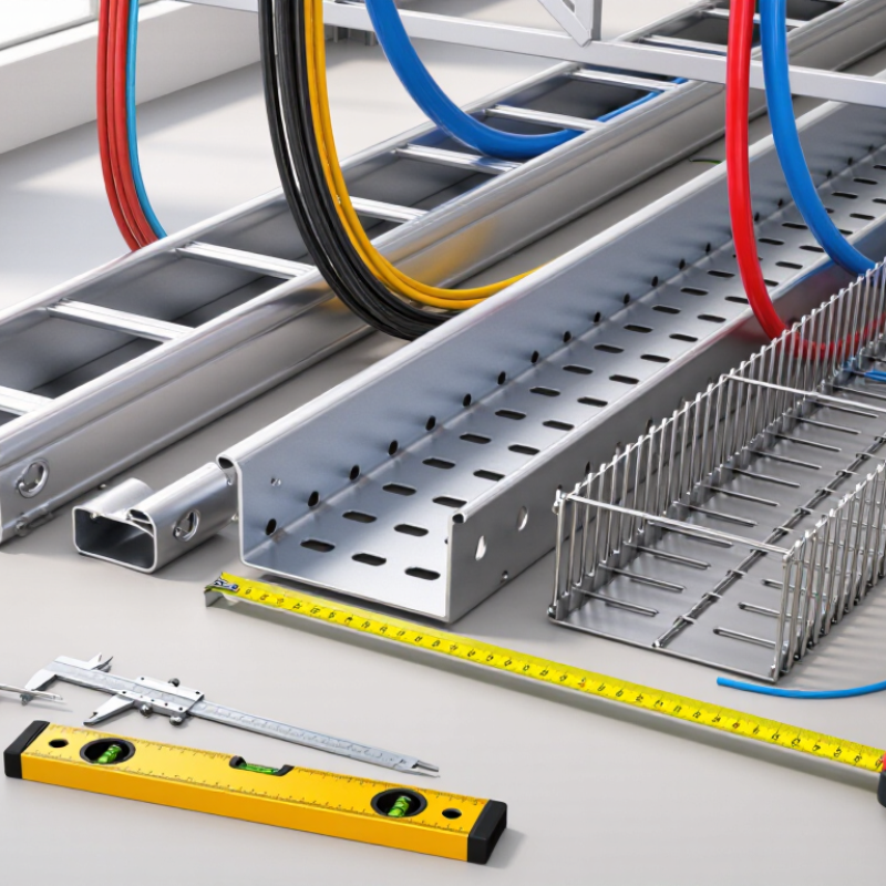
Choosing a steel cable tray starts with the cable type, not the lowest purchase price. Ladder tray suits power cables, control cables, and installations needing airflow. Its open rungs support long cable runs and simplify visual inspection. It also helps reduce heat buildup around heavily loaded conductors. According to the IEA Electricity 2024 report, data-center electricity demand could exceed 1,000 TWh by 2026. Higher equipment density makes ventilation and separation more important than before. Allow clearance for bend radius and future cables. That detail is often missed.
Trough tray provides greater protection from falling dust and light mechanical contact. It works well for instrumentation, communication, and smaller control cables. Use dividers when power and signal circuits share one route. Solid-bottom tray offers the strongest protection against dust, dripping contaminants, and cable sag. It fits sensitive wiring, but heat dissipation is weaker. The choice is not always obvious. IEC 61537 testing guidance emphasizes load, deflection, electrical continuity, and corrosion performance. NEMA VE 1 also provides practical requirements for tray construction and support spacing. Review those requirements against the project environment, cable weight, and span length. In humid areas, coated steel may outperform untreated steel, yet coating damage during cutting can create weak points. I have seen layouts fail because installers could not access fasteners after cable placement. Leave working space. A neat drawing can still produce an awkward installation.
How to Choose the Right Steel Cable Tray for Your Project - Select Ladder, Trough, or Solid-Bottom Designs for Cable Types
| Tray Design | Typical Cable Types | Ventilation and Heat Dissipation | Cable Support and Protection | Recommended Applications | Main Advantages | Key Limitations | Relative Installation Effort | Selection Guidance |
Ladder Cable Tray
Two longitudinal side rails connected by regularly spaced rungs. | Power cables, medium-voltage cables, control cables, instrumentation cables, and large multi-core cables. | Excellent airflow around the cables. The open structure helps reduce heat buildup and supports ampacity management when cable spacing and loading follow the applicable electrical code. | Provides strong support at the side rails and rungs. Cables can be secured with approved ties or cleats, and the rungs provide convenient access for routing. | Industrial plants, substations, utility facilities, data centers, commercial buildings, and long cable runs with frequent access requirements. | - High ventilation
- Easy cable installation and inspection
- Convenient cable segregation and routing
- Suitable for heavy cable loads when properly engineered
| - Offers less protection from falling dust, dripping liquids, and small objects
- Small cables may require additional support or mesh accessories
- May require covers in contaminated or outdoor areas
| Low to Medium | Choose ladder tray when heat dissipation, heavy cables, accessibility, and future cable additions are the highest priorities. |
Trough Cable Tray
A ventilated channel with a continuous or partially continuous base and side walls. | Control cables, instrumentation cables, communication cables, smaller power cables, and grouped low-voltage wiring. | Good ventilation through side openings or perforations. Heat dissipation is generally lower than with ladder tray but higher than with a solid-bottom design. | Provides continuous or near-continuous bottom support, helping prevent smaller cables from sagging through openings. Cable retention is improved compared with widely spaced rungs. | Commercial facilities, building services, control rooms, process-control systems, and installations containing many small or delicate cables. | - Good balance of ventilation and cable support
- Helps protect smaller cables from falling through the tray
- Neat appearance for grouped wiring
- Suitable for mixed control and low-voltage cable routes
| - Reduced airflow compared with ladder tray
- Less suitable for very high cable heat loads unless carefully calculated
- Access to cables may be slower than with a fully open ladder design
| Medium | Choose trough tray when continuous support and moderate ventilation are needed for control, instrumentation, or smaller cable groups. |
Solid-Bottom Cable Tray
A tray with a continuous base and side walls, normally used with or without a removable cover. | Sensitive instrumentation cables, low-voltage control cables, communication cables, fiber-optic cables, and wiring requiring greater environmental shielding. | Limited natural airflow. Cable temperature and allowable current-carrying capacity must be evaluated carefully, particularly when cables are densely packed or covered. | Continuous bottom support protects small cables and reduces exposure to debris, dripping contaminants, and accidental contact from below. A cover can provide additional protection. | Clean rooms, indoor control systems, areas with falling dust or liquids, low-voltage communication routes, and locations where cable protection is more important than ventilation. | - Strong continuous support for small cables
- Improved protection from dust and falling objects
- Suitable for covered cable routes
- Helps maintain orderly separation of sensitive wiring
| - Lowest ventilation of the three designs
- May require derating or increased tray size for heat-generating cables
- Water or condensation can collect if drainage is not provided
- More time may be needed for cable access and maintenance
| Medium to High | Choose solid-bottom tray when continuous support and environmental protection are more important than maximum heat dissipation. |
Project Selection Notes: Confirm the required tray width, side-rail height, span, cable fill, concentrated loads, corrosion environment, grounding and bonding method, fire requirements, and applicable electrical standards before final selection. Cable ampacity and spacing should be verified by a qualified electrical designer, especially for solid-bottom and covered installations.
Choose Steel Coatings Using ASTM A123 and ISO 12944 Corrosion Classes
Choosing the right steel cable tray begins with understanding its corrosion environment. ASTM A123 is useful when the tray or its supports require hot-dip galvanized steel. It sets requirements for coating thickness, appearance, and inspection. The required thickness depends on the steel section. Ask for coating records, not only the word “galvanized.” Check the edges and joints.
Environmental Exposure ISO 12944 helps classify atmospheric exposure. C1 describes dry, clean interiors. C2 covers low exposure, while C3 indicates moderate humidity or urban conditions. C4 applies to industrial areas and coastal locations. C5 and CX represent very severe or offshore environments. These classes guide protective paint systems and expected durability. They do not replace project-specific engineering. Humidity changes everything.
For a ventilated indoor facility, an ASTM A123 galvanized tray may provide practical protection. Outdoor coastal routes may need a thicker zinc coating, a duplex system, or another approved material. Consider salt deposits, chemicals, standing water, and abrasion from cable installation. Protect cut edges and repair damaged areas according to the coating specification. I once treated a sheltered plant room as C2; condensation proved otherwise. That mistake changed the inspection plan. Fasteners also matter. A strong tray can fail early when incompatible hardware creates galvanic corrosion. Review drawings, environmental data, coating certificates, and maintenance access before ordering. Some assumptions will still be wrong. Allow room to revise them.
Verify Safety, Grounding, and Mechanical Performance Under IEC 61537
Selecting a steel cable tray starts with IEC 61537, not with appearance or price. The standard covers load capacity, mechanical strength, electrical continuity, and resistance to environmental stresses. Check the manufacturer’s tested safe working load at your actual span. A tray rated at 150 kg per metre may perform differently when supports are spaced farther apart.
Grounding needs equal attention. IEC 61537 includes continuity requirements for metallic tray systems, but local electrical rules still apply. Bond joints with suitable conductors where paint, movement, or corrosion could interrupt continuity. Verify resistance with a calibrated tester after installation. Do not assume that bolted contact is automatically reliable. It sometimes is not.
Corrosion deserves a physical review. The NACE IMPACT study estimated global corrosion costs at about 2.5 trillion US dollars annually, equal to roughly 3.4% of global GDP. Select galvanized, stainless, or coated steel according to humidity, chemicals, salt exposure, and temperature. Inspect cut edges and damaged coatings. Mechanical checks should include deflection, impact risk, ladder rung strength, and fastener security. IEC 61537 test results are useful, but they may not represent every site condition. That is the uncomfortable part. A compliant tray can still fail when installation details are ignored.