








Choosing Transformer Switch Gear is a project decision that affects safety, reliability, maintenance, and future operating costs. The right choice depends on more than voltage ratings. Engineers must consider system voltage, load current, fault levels, switching frequency, installation conditions, and the transformer’s operating requirements. A unit installed in a damp outdoor enclosure may need different protection and insulation than equipment in a clean indoor substation. Small details matter.
This guide introduces the main factors behind a sound selection, including switchgear type, rated capacity, protection coordination, enclosure design, and maintenance access. It also explains why project drawings and verified equipment data should be reviewed together, rather than treating a catalog specification as the whole answer. Manufacturer documentation and applicable technical standards provide essential references; qualified electrical professionals should confirm the final design for the specific site. That check is worth the time.
No single configuration suits every project. A choice that works well for a compact commercial installation may not fit an industrial facility with higher fault exposure or demanding service conditions. Budget matters, but a low purchase price can overlook downtime, spare parts, and inspection needs. I have to admit that early estimates can miss these practical costs. The sections ahead offer a clear framework for comparing options, asking suppliers focused questions, and spotting assumptions that deserve a second look before equipment is ordered.
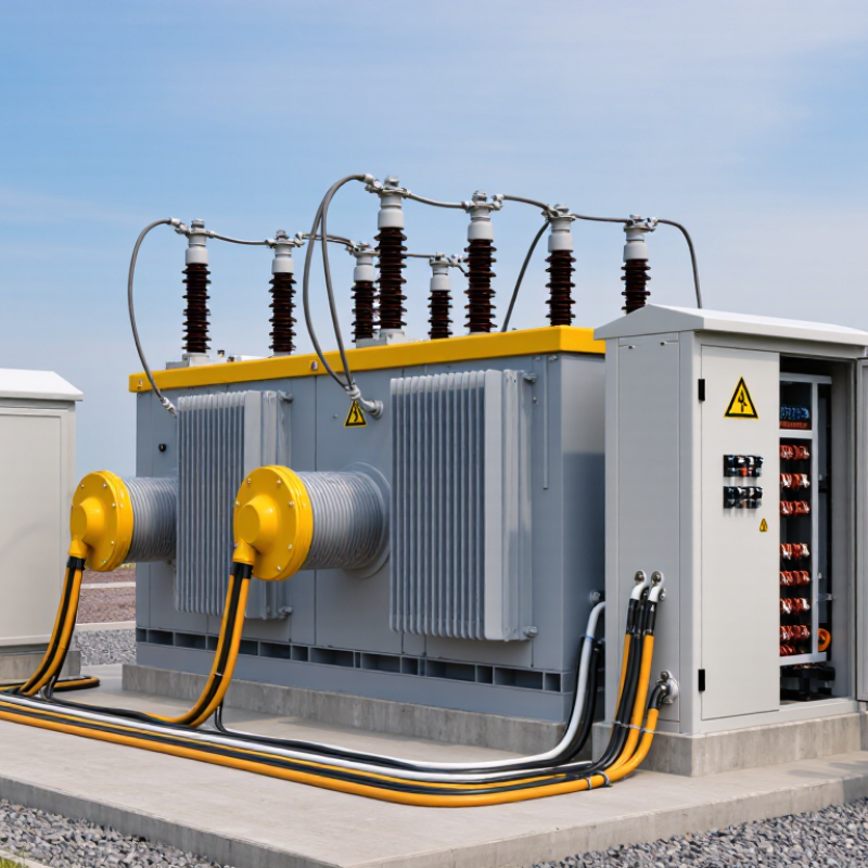
Begin with the transformer nameplate and the project’s actual load data. Record its kVA rating, primary and secondary voltages, phase, frequency, impedance, and grounding arrangement. Start with the load. A warehouse with large motors, for example, may draw modest steady current but create substantial starting demand. Note peak loads, expected inrush, and any planned equipment additions.
Then identify the switchgear’s operating and fault conditions. Its continuous-current rating must suit the transformer and connected loads, while its interrupting rating must safely handle the available fault current at the installation point. Details matter. Confirm voltage class, insulation level, enclosure type, and environmental conditions, including dust, moisture, temperature, and available space.
Check how protective devices coordinate with upstream and downstream equipment; poor coordination can leave too much of a system disconnected after a fault. Verify utility requirements and applicable project standards with the responsible electrical engineer. One detail is easy to miss: transformer impedance affects fault-current estimates, so assumptions should be documented and checked against current system data. Allow for future capacity, but avoid oversizing without a clear technical reason. That judgment may need revision when the final load schedule arrives.
How to Choose Transformer Switch Gear for Your Project
Compare Switchgear Types and Operating Conditions
Switchgear selection starts with the transformer’s voltage, rated current, and available fault current. These values determine the equipment’s interruption and insulation requirements. For many medium-voltage applications, vacuum circuit breakers offer reliable switching with relatively modest routine maintenance. Air-insulated assemblies are often easier to inspect, but they need more installation space. Gas-insulated equipment can fit tight rooms, though service procedures and environmental controls require careful planning.
Conditions matter just as much as type. A dusty workshop, a damp basement, and an outdoor pad-mounted installation present different risks. Dust gets everywhere. Check enclosure ratings, ventilation, corrosion exposure, and temperature limits against the actual site. At higher altitudes, insulation performance may need adjustment. Leave adequate clearance for cable bends and safe maintenance access; a layout that fits on paper can still frustrate technicians.
Review switching duty and protection coordination with the transformer, not in isolation. Magnetizing inrush can affect relay settings, while frequent motor starts or load changes may increase switching demands. Confirm that the switchgear’s short-circuit rating matches the system study, and verify its control supply and interlocks. Field experience helps here: small installation details often cause delays. Still, assumptions from a similar project can mislead, so verify the site conditions before finalizing specifications.
Transformer switchgear should match the transformer and the network it serves. Check rated voltage, continuous current, insulation level, and short-circuit withstand capacity against project data. A unit that fits the normal load may still be unsuitable for a high fault level. Include expected load growth, transformer inrush, and site conditions in the review. Outdoor equipment may need different environmental protection than gear installed in a clean electrical room. Small details matter.
Tips: Confirm phase, frequency, grounding method, and connection arrangement. Compare available fault current with the switchgear rating. Ask the project engineer to verify protection settings against the transformer data and upstream devices. Keep the calculations and equipment documents together.
Protection should isolate faults without causing needless outages. Review breaker or fuse characteristics, relay functions, and coordination across the system. Check that the chosen arrangement can detect relevant faults while tolerating normal energization current. Then confirm interfaces, control power, cable entry, and installation clearances. These are easy to overlook on a drawing. Compatibility is not just a voltage match; it includes how the gear connects, operates, and can be maintained. If project data is incomplete, pause and resolve the uncertainty before specifying equipment. I would not treat a familiar configuration as proof that it suits this installation.
Example selection checklist for medium-voltage transformer applications. Values are illustrative; confirm final ratings against the utility data, fault study, applicable standards, and project specifications.
| Selection check | Example project data | What to verify |
|---|---|---|
| System voltage and equipment class | 11 kV nominal system; 12 kV class switchgear | Match the switchgear rated voltage and insulation level to the system’s highest operating voltage and applicable insulation-coordination requirements. |
| Frequency and phase | Three-phase, 50 Hz supply | Confirm the switchgear, instrument transformers, relays, and transformer are designed for the same system frequency and phase arrangement. |
| Transformer load current | 1,000 kVA transformer at 11 kV: approximately 52.5 A full-load primary current | Calculate current using the transformer rating and system voltage. Select feeder components and protection settings for the expected load and permitted overloads. |
| Continuous current rating | Example: 630 A switchgear busbar and circuit-breaker rating | A standard switchgear rating can be much higher than transformer full-load current. Check future load growth, busbar loading, ambient-temperature derating, and connection ratings. |
| Short-circuit withstand | Illustrative rating: 20 kA for 1 s | Use the prospective fault current from the utility or network study. Check the switchgear short-time withstand, peak withstand, and circuit-breaker breaking capacity against that study. |
| Switching and protection method | Vacuum circuit-breaker feeder with protection relay for a transformer feeder | Select a circuit-breaker or fuse-switch arrangement based on transformer size, fault levels, operating requirements, and coordination with upstream and downstream protection. |
| Protection functions and coordination | Common functions include phase overcurrent and earth-fault protection; transformer differential or temperature protection may be specified for suitable applications. | Confirm relay functions, CT ratios, trip settings, and time-current coordination with the transformer protection scheme and the wider network protection study. |
| Earthing and neutral arrangement | Example: solidly earthed or impedance-earthed network, as defined by the project | Verify the system earthing method, earth-fault current, earthing-switch duty, cable-screen bonding, and relay sensitivity. Do not assume all networks use the same arrangement. |
| Physical and installation compatibility | Indoor metal-enclosed lineup with cable entry and panel layout defined by the site design | Check enclosure rating, ambient conditions, altitude, ventilation, access clearances, cable type and entry, phase arrangement, interlocks, and extension requirements. |
| Standards and verification | IEC 62271-200 for AC metal-enclosed switchgear; IEC 62271-100 for AC circuit-breakers; IEC 60076 for power transformers | Confirm the editions and standards required by the local authority and project. Review type-test evidence, routine-test records, and interface drawings before approval. |
Final equipment selection should be reviewed by a qualified electrical engineer using the project’s load schedule, network fault study, protection-coordination study, and local electrical requirements.
Before selecting transformer switchgear, check the actual site: available floor space, cable-entry direction, lifting access, ventilation, and clearance from walls. A unit that fits on a drawing may block a maintenance aisle in reality. Verify system voltage, grounding method, fault current, and protective-device coordination with the project engineer. Specify arc-flash controls and interlocks for the operating conditions, not just the equipment label. Keep it practical.
Maintenance access matters. Can technicians inspect connections, test protection, and isolate the equipment without moving nearby machinery? Include safe working space, clear labeling, and room for test leads. The U.S. Department of Energy’s 2013 distribution-transformer standards analysis projected about 3.6 quadrillion Btu in cumulative energy savings over 30 years from improved efficiency. That projection is not a site-level guarantee, but it shows why losses belong in lifecycle comparisons. Review the report’s assumptions against expected loading and operating hours. Sealed equipment may reduce some routine tasks, yet it does not eliminate inspections or condition checks. I would not treat a maintenance schedule as fixed; site conditions, load history, and manufacturer-neutral test guidance should shape it. Small detail, big consequence. A drain pan, awkward door swing, or inaccessible grounding point can turn a routine inspection into a workaround.
Compare the IEC voltage scopes as an initial step in selecting switchgear. Voltage class is only one consideration; confirm the project’s installation, safety, and maintenance requirements before specifying equipment.
Installation: Check indoor or outdoor location, available space, access, clearances, and environmental conditions.
Safety: Verify rated voltage, insulation level, short-circuit withstand, protection, and applicable local requirements.
Maintenance: Consider safe access, inspection needs, spare parts, and the maintenance procedures required for the selected equipment.
Choosing transformer switchgear starts with the project’s electrical data, not a catalog image. Confirm system voltage, continuous current, insulation level, and the available fault current. Check the required switching and interruption duties. A qualified electrical engineer should verify ratings against the transformer and the wider protection scheme. Check the nameplate.
Compliance depends on location and installation. Identify the standards, utility requirements, and local codes that apply to the project. Then confirm that the proposed equipment configuration—not just a similar product family—has supporting documentation. Review drawings, test records, and declared ratings. Requirements can change between jurisdictions, so assumptions need checking.
Physical fit matters just as much. Measure the room, including door openings, working clearances, and space for cable bending and termination. Check cable routes. Confirm indoor or outdoor suitability, ambient temperature limits, ventilation, and exposure to dust or moisture. Ask how protection settings coordinate with transformer inrush and downstream devices. Small details matter. A schedule may still miss a site constraint, so compare the final layout with actual site measurements before approval.
Hein Minnie
Cell nr: +27 (0) 82 564 6501
Email: sale@thecirclemachine.com
Hein Minnie Jnr
Cell nr: +27 (0) 84 284 7234
Email: sale@thecirclemachine.com
Address:
10 Apsey Street,
Heidelberg,
Gauteng,
1441
Bendet Engineering Services (PTY) LTD was established in 1987. Our team of engineers and draughtsman are ready to deliver a complete turnkey solution, from the design phase to commissioning. A dedicated team that consists of electrical, mechanical and industrial engineers, we are able to offer a comprehensive service to our clients.