








A Hydraulic Piling Rig installs piles that transfer a structure’s load through weak or variable surface soil to stronger ground below. On a building site, the rig may stand beside a marked pile position, lower a steel casing, and press or drive the pile into the earth. The exact method depends on the rig, pile design, ground conditions, and project requirements.
The work is practical and highly site-specific. Operators monitor alignment, penetration, and machine response while the crew checks each pile against the design. Small changes matter. A pile that drifts off line can complicate later construction, even when the rig appears to be working smoothly. That is one reason experienced supervision and suitable ground assessment are essential.
A Hydraulic Piling Rig is commonly used for building foundations, bridges, retaining structures, and other projects that need deep support. It can help install piles in confined or demanding locations, but it is not a universal solution. Soil layers, access, noise limits, and nearby structures may affect equipment choice and installation technique. There is no verified expert quotation or source material in the request, so I won’t invent a named specialist or attribute fabricated words. A sourced quotation would strengthen this introduction—and should be checked before publication.
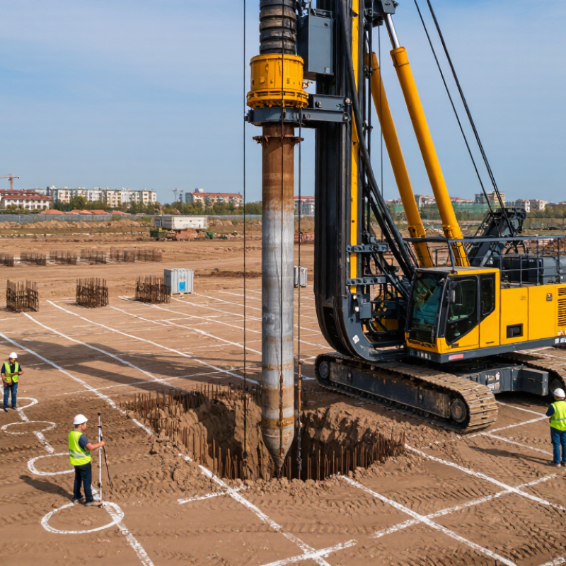
A hydraulic piling rig is a machine designed to install piles in the ground using hydraulically powered equipment. A pump moves pressurized fluid through hoses to cylinders or motors, which operate the rig’s working attachments. These may drive, press, vibrate, or drill piles, depending on the rig and its configuration. That is the basic idea.
Most rigs have a stable carrier, a tall mast or leader, and controls for positioning the pile. The mast helps keep the pile aligned as it enters the ground. Attachments vary: one setup may use a hydraulic hammer, while another uses an auger or pressing system. Some rigs handle steel sections; others are configured for concrete or timber piles. The machine is not one fixed design.
On site, operators adjust the rig to suit the pile, ground conditions, and available working space. Hydraulic controls allow measured movement, but they do not remove the need for careful setup. Soil conditions matter. A pile may meet dense layers or buried obstructions, and the rig’s response can change noticeably. This is why a simple description can feel incomplete: the same machine may perform very different tasks after its attachment and operating method are changed.
A hydraulic piling rig installs piles that support foundations for structures such as buildings, bridges, retaining walls, and solar installations. Depending on its configuration, it can drive or press piles into the ground. The bars show the typical order of operations, not time or frequency.
A hydraulic piling rig installs foundation piles by applying controlled force, rotation, vibration, or impact. The attachment and ground conditions determine the method. On site, the operator aligns the rig with the pile position and checks that the mast is vertical. Clamps hold the pile as hydraulic cylinders press it down, or a rotary head turns a helical pile into the soil. The pile transfers building loads through weaker layers to stronger ground, or distributes them along its shaft. Ground varies. The FHWA’s 2016 Design and Construction of Driven Pile Foundations manual describes three common driven-pile types: steel H-piles, steel pipe piles, and precast concrete piles. Selection depends on the design and soil profile.
During installation, crews track pile depth, alignment, and resistance. A hydraulic pressure reading is useful, but it does not prove the pile’s load capacity by itself. FHWA guidance also describes wave-equation analysis and field records for assessing driven-pile installation. Where verification is required, ASTM D1143/D1143M provides procedures for static axial compression testing; project protocols may test a pile to 200% of its design load. Small alignment errors can matter. The drawing may look exact, but soil layers shift, and the operator must respond to what the rig encounters. A clear installation record helps engineers compare actual conditions with the design.
Hydraulic piling rigs create deep foundations where surface soil cannot safely support a structure. Depending on their attachments, they can rotate augers, bore holes, or press piles into the ground. The method depends on the soil and project design. A rig is not a one-size-fits-all solution.
On building sites, contractors use these rigs to install piles beneath apartment blocks, warehouses, and bridges. The piles transfer loads to stronger soil or rock below. Along roads and railways, rigs may support retaining walls, noise barriers, or foundations for signs and lighting.
Near rivers and ports, suitable equipment can install piles for quays and other waterfront structures. Tight sites are common. Compact rigs can help where overhead clearance or access is limited, though setup still needs careful planning.
Before work begins, engineers review ground investigation results and check for buried services. Operators then position the rig, monitor pile depth, and record installation details. These steps matter because unexpected gravel, soft layers, or groundwater can change how a pile behaves.
Noise and vibration also need attention near existing buildings. It is easy to assume the rig does most of the work. In reality, poor ground data or rushed positioning can undermine an otherwise well-planned installation. A small offset matters.
A hydraulic piling rig installs piles through controlled pressing, vibration, or impact, depending on its configuration. Common options include steel H-piles, tubular steel piles, precast concrete piles, and sheet piles. FHWA’s 2016 technical manual, Design and Construction of Driven Pile Foundations, covers three common driven-pile groups: steel H-sections, steel pipe, and precast concrete. It ties pile selection to soil resistance and installation response, rather than offering one capacity for every site. Final capacity requires project-specific investigation and testing.
In soft clay and loose sand, press-in equipment can advance piles with limited vibration, which may help near sensitive structures. Vibratory or impact systems may suit other conditions. Dense gravel, cobbles, shallow rock, and cemented fill can slow penetration or cause refusal. Not every site. Borehole logs, groundwater levels, and SPT results help engineers match the pile section and method to each soil layer. FHWA guidance also treats drivability as a design check, not merely an installation concern. A trial pile can reveal rebound, ground heave, or hidden obstructions before full production. That step is easy to underestimate.
| Pile Type or Method | Typical Uses | Ground Conditions It Can Handle | Rig Setup and Key Considerations |
|---|---|---|---|
| Bored cast-in-place piles | Building foundations, bridge supports, retaining structures, and projects requiring large-diameter or deep piles. | A broad range of soils, including clay, silt, sand, gravel, and some weathered rock, subject to the drilling tools and support method used. | A rotary piling rig uses augers, drilling buckets, or core barrels. Temporary casing or drilling fluid may be needed to keep unstable or water-bearing boreholes open. |
| Continuous flight auger (CFA) piles | Foundations in urban areas and other sites where continuous installation and reduced noise or vibration are useful. | Commonly suited to soft-to-firm cohesive soils and loose-to-medium dense granular soils. Groundwater can often be managed because concrete is pumped through the hollow auger as it is withdrawn. | Requires a CFA-capable rig, hollow-stem auger, and controlled concrete pumping. Cobbles, boulders, hard layers, and rock can restrict penetration or pile quality. |
| Cased bored piles | Deep foundations where the borehole needs support during drilling and concrete placement. | Useful in loose sands, soft soils, unstable ground, and water-bearing strata where an unsupported borehole may collapse. | The rig advances temporary or permanent casing with suitable rotary tooling. Casing size, depth, groundwater pressure, and extraction method need to be considered in the installation design. |
| Micropiles | Underpinning, restricted-access work, foundation strengthening, and projects where piles must be installed near existing structures. | Can be drilled through varied soils and into rock when matched with suitable casing, drilling tools, and grouting methods. | Requires a compatible small-diameter drilling setup and grout equipment. Capacity depends on the design, reinforcement, grout bond, and verified ground conditions. |
| Driven precast concrete or steel piles | Foundations where piles are installed by impact rather than excavating a borehole. | Often used in soft soils and granular deposits. Dense layers, cobbles, boulders, or shallow rock may cause refusal or damage and need assessment. | A hydraulic piling rig must be fitted with a suitable hydraulic hammer or other driving system. Installation can create noise and ground vibration; driving records help verify performance. |
| Hydraulically pressed piles | Sites with strict noise and vibration limits, including work near sensitive buildings or in built-up areas. | Most practical where the ground and pile design allow steady penetration. Hard obstructions and very dense layers can prevent installation. | A press-in system needs a suitable reaction frame or anchorage, often provided by previously installed piles. Access, reaction capacity, and obstruction risk should be checked in advance. |
Note: “Hydraulic piling rig” can describe different equipment configurations. The pile method and achievable ground conditions depend on the rig, attachments, pile design, groundwater, and a site-specific geotechnical assessment.
A hydraulic piling rig uses pressurized fluid to operate a hammer, drilling attachment, or pile-pressing unit. Its exact task depends on the rig configuration and pile type. It can install foundation piles for buildings, bridges, retaining walls, and other structures. Hydraulic controls let operators adjust movement and force with useful precision. On suitable sites, this can improve alignment and reduce unnecessary repositioning. That saves time.
Benefits include strong force, steady control, and the ability to handle demanding ground conditions. Some press-in systems also create less vibration than impact driving, which can help near sensitive structures. But no method is quiet everywhere. Soil layers, pile dimensions, access, and nearby services all affect results. A compact rig may fit a tight work area, yet still need room for delivery, setup, and safe movement.
Before work starts, crews should review ground data, confirm underground utilities, and check the working platform’s bearing capacity. Hydraulic hoses, connections, filters, and fluid levels need regular inspection. Leaks or contaminated fluid can reduce performance and create hazards. The mast must stay aligned, and the rig must be stabilized as specified by its operating instructions. Operator training matters. In practice, production pressure can make routine checks feel easy to skip; that is when small faults become costly.
Hein Minnie
Cell nr: +27 (0) 82 564 6501
Email: sale@thecirclemachine.com
Hein Minnie Jnr
Cell nr: +27 (0) 84 284 7234
Email: sale@thecirclemachine.com
Address:
10 Apsey Street,
Heidelberg,
Gauteng,
1441
Bendet Engineering Services (PTY) LTD was established in 1987. Our team of engineers and draughtsman are ready to deliver a complete turnkey solution, from the design phase to commissioning. A dedicated team that consists of electrical, mechanical and industrial engineers, we are able to offer a comprehensive service to our clients.