







When machinery must transmit torque while accommodating changes in distance, shaft selection affects reliability, noise, and maintenance. A Sliding Drive Shaft uses a splined or telescoping section to transfer rotation while allowing controlled axial movement. This design is common in applications where suspension travel, equipment articulation, or thermal movement changes the distance between connected components. The shaft can extend and retract as needed. That matters.
Choosing one involves more than matching end connections. Engineers should check required torque, rotational speed, travel range, operating angles, and available space. They should also consider the duty cycle, exposure to dust or moisture, and the maintenance routine. A shaft that fits on paper may still create vibration or wear if alignment, balance, or lubrication is overlooked. Small details count.
The right design can help maintain power transmission as connected parts move, but it is not automatically the best option for every system. A fixed-length shaft may suit a stable installation better, while excessive sliding travel can introduce other design concerns. Check manufacturer specifications and have the complete driveline reviewed for the actual operating conditions. If the application includes sharp movement or heavy loads, careful validation is especially important. Fit comes first. This practical assessment helps teams choose a Sliding Drive Shaft that suits the machinery, rather than relying on a general claim or a quick visual match.
What Is a Sliding Drive Shaft?
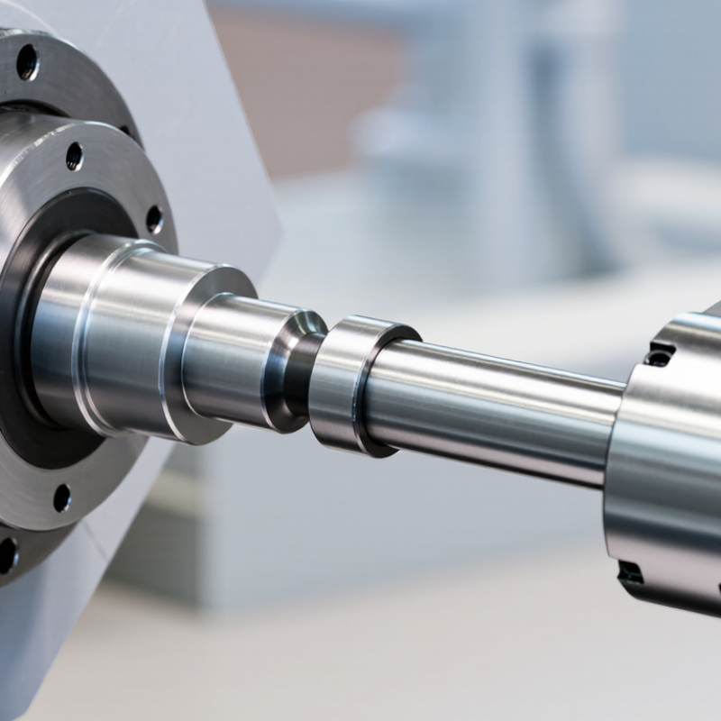
A sliding drive shaft is a torque-carrying shaft that can also change length. Its inner and outer splined sections slide against each other, allowing axial movement while the shaft rotates. In a vehicle, that movement can accommodate suspension travel and shifts in the distance between drivetrain components. In industrial equipment, it can help manage movement between connected machines. The splines must transmit torque while sliding; wear, contamination, or poor alignment can make movement stiff and noisy. That sounds simple. It isn’t always.
ISO 4156 specifies dimensions and fits for straight-sided involute splines, which are used in some sliding shaft designs. Correct fit matters: excessive clearance can increase impact and backlash, while tight fits may resist axial travel. The U.S. Department of Energy’s “Where the Energy Goes: Gasoline Vehicles” estimates that roughly 5–6% of vehicle energy is lost through the drivetrain. That figure describes the drivetrain overall, not a sliding shaft alone. A telescoping shaft does not erase those losses; it solves a different problem by accommodating length change while carrying torque.
Tips: Check axial travel, torque demand, operating angle, and lubrication requirements together. Look for polished wear marks or rust around the sliding section during inspection. A shaft that moves by hand when unloaded may still bind under torque, so verify it in its actual operating setup.
| Dimension | Details | Why It Matters |
|---|---|---|
| Definition | A sliding drive shaft is a shaft assembly designed to transmit rotary torque while allowing its effective length to change. Axial movement is commonly provided by a splined slip joint or a telescoping shaft section. | It accommodates movement between connected components without requiring the shaft to remain at one fixed length. |
| How it works | The sliding sections move in or out along the shaft axis while their engaged splines or profiles continue to transfer rotation and torque. | The joint must have enough usable travel for the application and remain properly engaged throughout that travel. |
| Typical applications | Vehicle propeller shafts, agricultural equipment, construction machinery, and other driveline systems where connected components can move relative to one another. | It is useful when suspension travel, articulation, or machine movement changes the distance between drivetrain components. |
| Main benefit | Allows axial length changes while transmitting rotation, reducing the need for a rigid, fixed-length connection. | Can help a driveline accommodate movement that would otherwise place unwanted axial loads on connected components. |
| Length and travel | Required installed length and sliding travel depend on the equipment geometry and its full range of movement. The shaft should not bottom out or lose adequate engagement during operation. | Correct measurement helps prevent binding, separation, and damage to the shaft or connected components. |
| Torque capacity | Capacity depends on factors such as material, shaft diameter, wall thickness, spline design, joint construction, and operating conditions. | Selection should be based on the application’s torque and service requirements, not on sliding capability alone. |
| Alignment and operating angles | The shaft and its joints must operate within the alignment and angular limits specified for the particular equipment and joint design. | Incorrect angles or alignment can contribute to vibration, noise, and accelerated wear. |
| Maintenance considerations | Depending on the design, the sliding joint may require lubrication and inspection for wear, corrosion, looseness, or contamination. | Following the equipment maker’s maintenance guidance helps preserve smooth movement and reliable torque transfer. |
| When to choose one | Choose a sliding drive shaft when the distance between connected drivetrain components changes during normal operation and the assembly must continue transmitting torque. | Confirm the required travel, torque capacity, operating speed, joint angles, dimensions, and maintenance needs before selecting a design. |